
The construction process of Suspended metal ceiling
2024-06-19
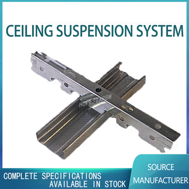
The construction process of suspended ceiling includes steps such as drawing the horizontal line of the ceiling elevation, installing suspension rods and keels, installing metal plates, adjusting and accepting, etc. The elevation and arching must meet the design requirements, and the materials must undergo rust prevention treatment. Quality standards include both main control items and general items, and finished product protection and safe construction are also important links in the construction process. During the construction process, green environmental protection measures should be taken to control construction noise, classify and store waste, clean up waste in a timely manner, and achieve civilized construction.
process flow
Ceiling elevation horizontal line - Draw keel dividing line - Install suspension rod - Install side keel - Install main keel - Install secondary keel
Installation of cover panel
1. Snap the horizontal line of the ceiling elevation
According to the floor elevation horizontal line, use a ruler to vertically vector to the design elevation of the ceiling, and snap the ceiling elevation horizontal line along the wall and around.
2. Draw keel dividing line
Pop out the main keel at the position of the concrete top plate according to the ceiling plan. The main keel should be divided from the center of the ceiling to both sides, with a maximum spacing of 1200mm, and the fixing points of the suspension rods should be marked with a spacing of 900-1200mm. If the fixing points of beams and pipelines exceed the design and regulatory requirements, additional fixing points for suspension rods should be added.
3. Installing suspension rods
After marking the horizontal line of the ceiling elevation and the position line of the keel, determine the elevation of the lower end of the suspension rod. According to the position of the main keel and the spacing between the suspension points, the spacing between the suspension points is 900-1200mm. Connect one end of the suspension rod to the floor slab and fix it (direct bolt or welding the suspension rod to the post embedded part fixed with expansion bolt can be used). And rust prevention treatment shall be applied to the steel bar suspension rod, and two coats of rust prevention paint shall be applied. The upper suspended ceiling adopts a diameter of 10mm suspension rod, while the non upper suspended ceiling adopts a diameter of P6-8mm suspension rod. The ceiling keel system with a suspension rod length greater than 1500mm should be equipped with reverse support. The suspended ceiling should be straight and have sufficient load-bearing capacity. The distance between the suspended ceiling and the end of the main keel shall not exceed 300mm, otherwise additional suspension rods shall be added. Additional suspension rods should be installed for lighting fixtures, air vents, and maintenance openings. Heavy lighting fixtures, fans, and other heavy equipment weighing more than 3kg are strictly prohibited from being installed on the keel of the suspended ceiling project. Additional suspension components should be installed to connect to the structure. 4.5 Installation edge not present
The side keel should be installed according to the snap line. The L-shaped galvanized light steel strip should be fixed to the embedded wooden brick along the control line of the side keel on the wall (column) with self tapping screws. If it is a concrete wall (column), it can be fixed with shooting nails, and the distance between shooting nails should not be greater than the distance between the secondary keel on the ceiling. If the cover panel is a fixed single aluminum plate or aluminum-plastic plate, it can be directly trimmed with sealant or decorated with internal corners.
4. Install the main keel
4.1 When installing the main keel, the hanging parts of the main keel should be connected to the main keel, the screws should be tightened, and the ceiling should be arched according to the design requirements. The arch height should be about 1/200 of the short span, and the spacing between the main keels should be less than 1200mm. The installed main keel joints should be staggered, and lifting points should be added at the joints to check the flatness of the keel at any time. The cantilever section of the main keel should not exceed 300mm, otherwise additional suspension rods should be added.
4.2 When encountering ventilation ducts that exceed the maximum spacing requirement of the keel, angle steel with a diameter of L30 × 3 or above must be used as the keel skeleton, and the skeleton cannot be in contact with equipment engineering such as ventilation ducts. For suspended ceilings with a span greater than 15m, a large keel should be added every 15m on the main keel, and connected firmly vertically to the main keel.
4.3 If the cover panel is a single aluminum plate or aluminum-plastic plate, steel or square aluminum pipes can also be used as the main keel, and connected to the crossbar with a dedicated elevator or bolt (riveted).
4.4 If a maintenance walkway is installed on the ceiling, an independent suspension system should be installed, and the materials for the maintenance walkway should be selected according to the design requirements.
5. Install secondary keel
5.1 When hanging the secondary keel, construction should be carried out according to the spacing between the secondary keels specified in the design. The secondary keel of the strip or square metal cover panel should be directly connected to the main keel using matching specialized secondary keel products.
When using T-shaped galvanized special connectors to fix the secondary keel to the main keel, both ends of the secondary keel should be overlapped on the horizontal flange of the L-shaped edge keel.
5.3 Additional keels should be installed around ventilation, water and electricity openings, and the connectors of the additional keels should be fixed with rivets or screws.
process flow
Ceiling elevation horizontal line - Draw keel dividing line - Install suspension rod - Install side keel - Install main keel - Install secondary keel
Installation of cover panel
1. Snap the horizontal line of the ceiling elevation
According to the floor elevation horizontal line, use a ruler to vertically vector to the design elevation of the ceiling, and snap the ceiling elevation horizontal line along the wall and around.
2. Draw keel dividing line
Pop out the main keel at the position of the concrete top plate according to the ceiling plan. The main keel should be divided from the center of the ceiling to both sides, with a maximum spacing of 1200mm, and the fixing points of the suspension rods should be marked with a spacing of 900-1200mm. If the fixing points of beams and pipelines exceed the design and regulatory requirements, additional fixing points for suspension rods should be added.
3. Installing suspension rods
After marking the horizontal line of the ceiling elevation and the position line of the keel, determine the elevation of the lower end of the suspension rod. According to the position of the main keel and the spacing between the suspension points, the spacing between the suspension points is 900-1200mm. Connect one end of the suspension rod to the floor slab and fix it (direct bolt or welding the suspension rod to the post embedded part fixed with expansion bolt can be used). And rust prevention treatment shall be applied to the steel bar suspension rod, and two coats of rust prevention paint shall be applied. The upper suspended ceiling adopts a diameter of 10mm suspension rod, while the non upper suspended ceiling adopts a diameter of P6-8mm suspension rod. The ceiling keel system with a suspension rod length greater than 1500mm should be equipped with reverse support. The suspended ceiling should be straight and have sufficient load-bearing capacity. The distance between the suspended ceiling and the end of the main keel shall not exceed 300mm, otherwise additional suspension rods shall be added. Additional suspension rods should be installed for lighting fixtures, air vents, and maintenance openings. Heavy lighting fixtures, fans, and other heavy equipment weighing more than 3kg are strictly prohibited from being installed on the keel of the suspended ceiling project. Additional suspension components should be installed to connect to the structure. 4.5 Installation edge not present
The side keel should be installed according to the snap line. The L-shaped galvanized light steel strip should be fixed to the embedded wooden brick along the control line of the side keel on the wall (column) with self tapping screws. If it is a concrete wall (column), it can be fixed with shooting nails, and the distance between shooting nails should not be greater than the distance between the secondary keel on the ceiling. If the cover panel is a fixed single aluminum plate or aluminum-plastic plate, it can be directly trimmed with sealant or decorated with internal corners.
4. Install the main keel
4.1 When installing the main keel, the hanging parts of the main keel should be connected to the main keel, the screws should be tightened, and the ceiling should be arched according to the design requirements. The arch height should be about 1/200 of the short span, and the spacing between the main keels should be less than 1200mm. The installed main keel joints should be staggered, and lifting points should be added at the joints to check the flatness of the keel at any time. The cantilever section of the main keel should not exceed 300mm, otherwise additional suspension rods should be added.
4.2 When encountering ventilation ducts that exceed the maximum spacing requirement of the keel, angle steel with a diameter of L30 × 3 or above must be used as the keel skeleton, and the skeleton cannot be in contact with equipment engineering such as ventilation ducts. For suspended ceilings with a span greater than 15m, a large keel should be added every 15m on the main keel, and connected firmly vertically to the main keel.
4.3 If the cover panel is a single aluminum plate or aluminum-plastic plate, steel or square aluminum pipes can also be used as the main keel, and connected to the crossbar with a dedicated elevator or bolt (riveted).
4.4 If a maintenance walkway is installed on the ceiling, an independent suspension system should be installed, and the materials for the maintenance walkway should be selected according to the design requirements.
5. Install secondary keel
5.1 When hanging the secondary keel, construction should be carried out according to the spacing between the secondary keels specified in the design. The secondary keel of the strip or square metal cover panel should be directly connected to the main keel using matching specialized secondary keel products.
When using T-shaped galvanized special connectors to fix the secondary keel to the main keel, both ends of the secondary keel should be overlapped on the horizontal flange of the L-shaped edge keel.
5.3 Additional keels should be installed around ventilation, water and electricity openings, and the connectors of the additional keels should be fixed with rivets or screws.
How thick is the light steel keel generally
Introduction to the dimensions of standard light steel keel ceiling
Related Article

Ceiling wall angle, also known as perimeter angle or L-angle, is an indispensable L-shaped metal profile for suspended drywall ceiling systems. Roll-formed from cold-rolled galvanized steel, ceiling wall angle is fixed along the wall perimeter to support the ends of main channels and furring channels,
Ceiling Wall Angle – Galvanized L-Shaped Perimeter Trim for Suspended Drywall Ceilings
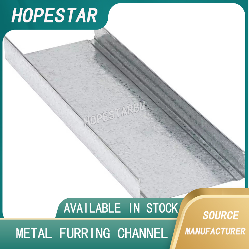
Galvanized steel profiles are the foundational metal framing components widely used in modern interior construction. Roll-formed from cold-rolled steel coated with protective zinc layer, galvanized steel profiles cover a full range of shapes including C studs, U tracks, omega channels,
Galvanized Steel Profiles – Reliable Cold Rolled Framing for Drywall Walls and Ceilings

Metal furring channel for ceiling is a vital secondary framing component widely used in suspended ceiling and drywall ceiling systems. Roll-formed from cold-rolled galvanized steel, this lightweight metal profile works together with main channels, hangers and wall angles to create a level,
Metal Furring Channel for Ceiling – Galvanized Secondary Framing for Suspended Drywall Ceilings

Metal omega channel, also widely called omega furring channel or hat channel, is an indispensable secondary metal framing profile for modern suspended ceilings and drywall wall furring systems. Named after its distinctive Ω shape, this profile is roll-formed from cold-rolled galvanized steel
Metal Omega Channel – Galvanized Omega Furring Channel for Drywall Ceiling and Wall Framing